Architects' Perspective |
||||||||||||||||
|
Page 23 / 25
 PART III MECHANICAL PERSPECTIVECHAPTER XXIIINTRODUCTIONHITHERTO we have considered perspective as an aid to drawing. Usually we supposed that we had an object in front of us—we sketched it—and then corrected our lines by the observance of those laws of nature that science has formulated. In an occasional excursion we started with the principal object of our composition and built up others around it by the application of perspective rules, common sense, and a little reasoning. Mathematical deduction of theory and artistic rendering have so little in common that there is always the danger of the former usurping the place of the latter if any other course than the one we took is followed. Architects' perspective. — At first sight perspective, as used by architects, seems a cold-blooded affair—a calculation of angles, a measuring of points ; the T-square and compasses for counsel ; while the man himself just rules the lines because he has not invented a machine to do it for him. But take his view of it. On a piece of tracing-paper are set out a ground plan, some elevations, and many details all measured out to scale. He and his centrolinead get to work and hey presto the blue smelly paper is converted to a drawing of a magnificent mansion which no man has ever seen ; substantial and realistic with every detail correct in its place—just as we should see it from the chosen point of view. Let us then apply the word mechanical to this branch of perspective not as an opprobrious epithet but just to distinguish it from its other and more tractable offshoot where our fancy and reason can have free play. It was our habitual custom in Part I to discover the reason for the length, depth, or direction of a line, and then to draw it by the method most applicable. It seems advisable instead of plunging into a different system for mechanical perspective to endeavour to 'keep up this good custom and even to pave the way by a compromise between the two methods.
If from that V.P. we run a line to our feet (" Painter ") we represent the actual direction of the line as it would be if we were standing on its near end. If from " Painter" we take a line at right angles to the other end, and continue it to the horizon, we find the second V.P. for the right angle. What we have done then is to set out a right angle at our feet in the actual position of the one we had to draw, but we copied the direction of one line first, in order to find V.P. 1, and consequently the position of the angle at " Painter."
A perspective drawing made from a plan and elevation of a building.—Let us (Fig. 355) represent the building we have to draw. Practice (Fig. 356). — Set out the ground plan of the building in the position it is to be drawn. Decide on the distance it is to be seen at, and mark our station point "P." Rule a horizontal base line touching the near corner to represent the base line of the picture plane, and another at P. Rule the line of sight perpendicular to these from P, and mark the P.V.P. From each corner of the plan take lines to P. In this way the position of each corner will be marked on the base line of the picture plane, and consequently the length of the front and side of the building just as we should see them if the picture plane were transparent. At P set out the right angle of the front side of the building in the same position as the plan (P—V.P. 2 parallel to 2-1 and P—V.P. 1 parallel to 2-3), and so find the two V.P.'s on the base line.  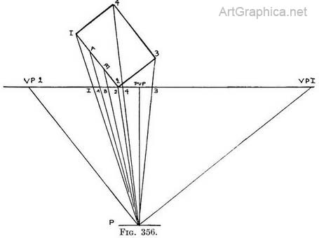
On a strip of paper[1] tick off each dimension found on the base line and mark them V.P.2, 1, A, B, 2,4, P.V.P., 3, V.P.1 (Fig. 357). Transfer these measurements to the base line in Fig. 35S. Where the near corner of the building is to come (at 2) raise its height by transferring the height of the side elevation. Decide how high up this wall the horizon line should be and draw it. Raise the V.P.'s from the ground line on to the horizon. 1 Fold a piece of paper quite flat, and use the folded edge for the measurements; it will be rigid, level, and straight. 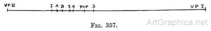
Draw the bottom and top lines of the end wall to V.P. 2, and those of the front wall to V.P. 1. Cut of the length of the front wall by a vertical line from the measurement found on the ground line (1), and the length of end wall by a vertical from its measurement (3). Fig. 355 represented the mere shell of a building, so that the explanation should be unmistakable. 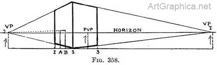
In Fig. 359 et seq., we have the same house with a gable roof, windows, and doors—quite a mansion—so carry on thus : Practice for Fig. 362.—Find measurement on ground as in Fig. 357, but add D for doorway and W for windows (Fig. 363). 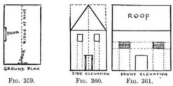
(The latter measurements being run down the wall of end elevation (dotted lines) to the ground plan.) As these points added to the others on the ground (Fig. 363) might cause confusion, it is advisable to make a separate tracing of them and to mark them on its ground line. The tracing is then laid over the perspective drawing, and these points pricked through on to its ground line when they are required. The outlets on the front elevation are added as required in the same way. The apex of the roof might have been included in the original drawing, but in the event of its having complicated features it is well to make a separate measurement on tracing-paper.
With this method we need not use either measuring points 01 diagonals to find the length of a receding line"!as we did in Part I. We simply raise a vertical line from each measured point on the ground line, and so cut off each receding line at the right place. HEIGHTS First method of measuring heights.—In a simple building all the heights can be measured off first on the elevation and then on to a vertical line at the near corner of the building on the perspective drawing. Each line starting from a measured height on the vertical (say of a chimney at the far corner) as it recedes to the V.P. will be cut at the proper distance by the vertical lines carried up from points on the ground line. In Fig. 364 the height of the chimney is shown on the elevation. The same point appears in the perspective drawing (Fig. 366). The line receding from chimney is cut at 2. by the vertical from its position on the ground line, and so the height of the chimney is obtained. 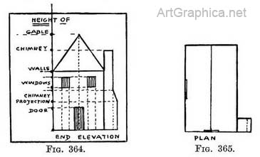
Second way of measuring heights. — Exercise. — To find the height of the weather-cock on the far corner of the building (Figs. 367, 368) the other heights and the ground line measurements having been determined as in previous examples. 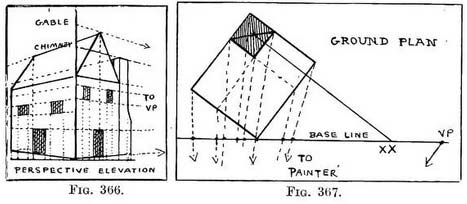
Practice. — From X, the position of the weather-cock on the plan (Fig. 367), carry a line parallel to the side of the building until it meets the base line (at XX). Mark it off on the ground line of the perspective drawing. Measure on the elevation the height of the weather-vane from the ground, and mark that height on an upright from X on the perspective drawing (Fig. 369). From its top carry a line to V.P. 2. Where it is cut by the upright which shews the position of the weather-vane On the ground line will be the desired height. 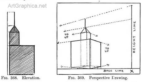
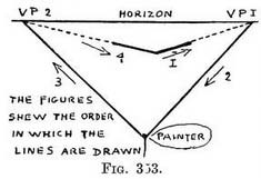
A shorter or longer perspective drawing is obtained by the building not touching the ground line. Usually the base line is drawn (as in Fig. 371) touching the near corner of the building, and it is the most convenient method. 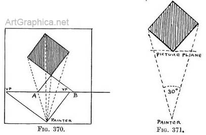
A greater length can be obtained for the picture plane by placing the plan in front of it, as shown by Fig. 373.
Next Page
Mechanical Perspective Prev Page Japanese Paintings
|
||||||||||||||||
 Suppose we have to draw a right angle lying on level ground with its corner towards us. If we copy the direction of one of the receding lines (Fig. 353) and continue it until it meets the horizon we find the V.P. for that line.
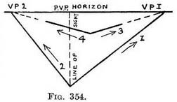 We might reverse the order and first set angle and continue its lines (Fig. 354) to find the two V.P.'s, then mark the corner of the right angle we have to draw and take it lines to the V.P.'s found by the angle at our feet. This is just what we do when we have no object to copy from.
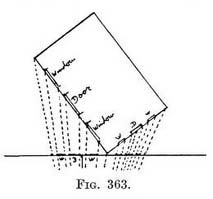 The height of the roof is obtained by the measurement of its front elevation, and adding that above the near corner of the house in the perspective drawing. A line from that height to V.P. 1 fixes the height of the gable above the centre of the end wall. A line from the gable apex to V.P. 2 determines the height and direction of the ridge.
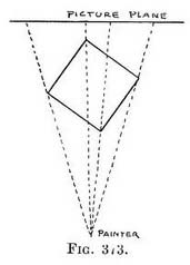 It the ground line with its measurements should make too long a line on the perspective drawing it can be reduced by placing the base line in the plan nearer to the painter (Fig. 370). But some way of representing the distance from the near corner of the building to the base line must be found. On the plan continue the side and end of the building until they meet the base line (at A and B) ; mark off these points with the others on the ground line of the perspective drawing.
 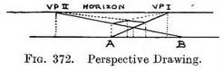 Start the receding line of the side of the house from B (taking it to V.P. 2) and the receding line of the
end from A (to V.P. 1) ; where these lines cross will be the house corner, at the correct distance from the ground line. The operation is equivalent to continuing the house up to the base line of the plan, and consequently starting it from the ground line in the perspective drawing.
Start the receding line of the side of the house from B (taking it to V.P. 2) and the receding line of the
end from A (to V.P. 1) ; where these lines cross will be the house corner, at the correct distance from the ground line. The operation is equivalent to continuing the house up to the base line of the plan, and consequently starting it from the ground line in the perspective drawing.


Online Art Books
Perspective for Artists Art Lessons Free Art Books Art Shop Art Links  
 |
